
Chapter 14 handles floor heating calculation. This assumes that you have read and are acquainted with the chapter 6. Room database, the chapter 11. Heat requirement calculation and chapter 12. U value calculation before you start this section.
The floor heating calculation is based on power requirement from heat requirement calculation, and U value calculation. The last one is only necessary for the floors where floor heating is to be calculated. When the power requirement is known, along with the definition of the layers with heat transmission in the floors,DDS-CAD will be able to calculate water quantity, pressure loss, surface temperature etc. for each single room. The floor heating calculation will also need data from a supplier. In this chapter we will present examples from the supplier Probata. Before you start the floor heating calculation, the power requirement must have been calculated, and you must set heat distribution. Heat distribution mentions the percentage of the floor area to get floor heating. Heat distribution can be set for each single room, each single layer, each single storey or for the entire building, and you find this function in the Building dialog
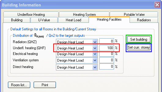
The tab "Heating Facilities". Here you decide what part of the building that is to get floor heating. The button "Set building" sets the distribution for the entire project, while "Set current storey" sets the distribution for the active storey.
When the heating facilities are set, go to the tab "U value". You must setup in DDS-CAD the layers in the floor, and in which layer you want to insert floor heating pipes.
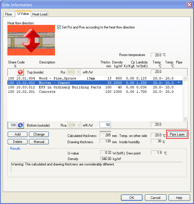
The layers in floor have been defined, and the U value has been calculated. Press the button "Pipe layer" to define which layers the pipes should be inserted in.
See video for defining which layers the pipes should be inserted in.

Click to see a video
The next step is to select the tab "Underfloor heating". First, select the supplier of the floor heating system.
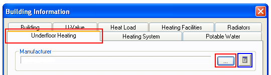
Before selecting the manufacturer, first load the additional product database.
See video how to get the manufacturer.
Click to see a video
Then select distributors and position them in the building.
Click to see a video
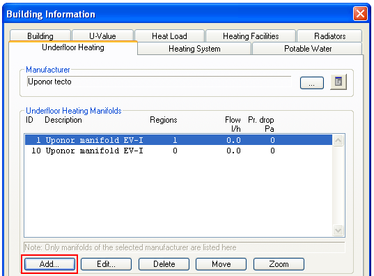
Press the button "Add" to position the distributors in the building.
When you have performed a heat requirement calculation, the rooms in the building have been defined as well. We can let DDS-CAD find the areas by clicking in the rooms that we want to be heated, or we can define our individual floor heating areas.
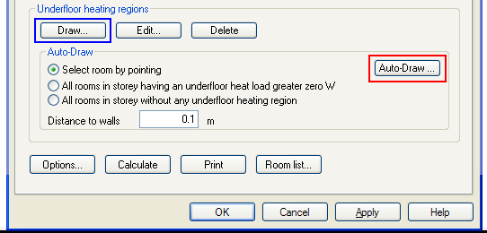
Area definition in DDS-CAD floor heating calculation.
The button Draw will allow you to defined individual free areas.
Click to see a video
Auto-draw will automatically generate floor heating area by 1)clicking in a room, 2)set all rooms in the storey with power requirement, or 3)all rooms in the storey with no floor heating definition. See video to select room with click on the mouse.
Click to see a video
You can, while defining an area, enter which type of pipe you want to use. You are allowed to change type by double-clicking on the area.

Double-click on an area to edit properties. Select type of pipe from the product database.
When all the areas have been defined, press the button "Setup" to enter supply and return temperature.
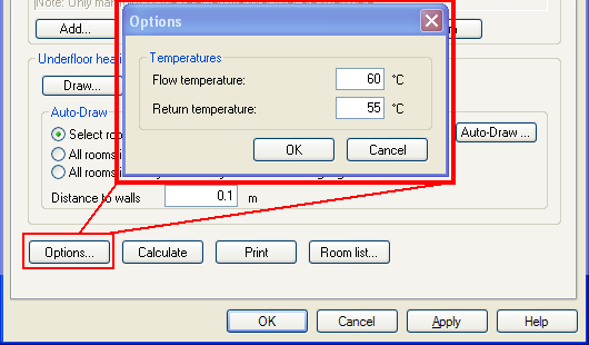
Supply and return temperature.
The floor heating system is now ready to be calculated. Press the button "Calculate". To see the calculation result for each area, double-click on the hatch.
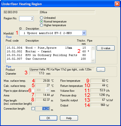
Calculation results.
1 Distributor - which distributor the area belongs to
2 Pipe layer - a * displays in which layer the pipes are positioned
3 Pipe diameter - Displays pipe dimension selected before the calculation
4 Max surface temp. - Information from the supplier
5 Calc surface temp. - Actual surface temp calculated by DDS-CAD
6 Pipe to Pipe distance - Floor heating calculation finds the best suitable pipe spacing distance in the data from the supplier. This can be overruled from the room dialog. See further down
7 Area - area for the floor heating circuit
8 Pipe length - Number of pipe meters included feed pipe from distributor
9 Flow temperature - as you entered under "Setup" before the calculation
10 Return temperature - The real calculated return temp
11 Volume Flow- Calculated quantity of water, litre/hour
12 Pressure drop - Calculated pressure loss from this circuit
13 and 14 - Specific and total power from the heat requirement calculation.
Depending on how many circuits you have connected to the distributors in your project, DDS-CAD will calculate and sum up results such as water quantity and pressure loss. Double-click on a distributor and select the flag "Calculation results".
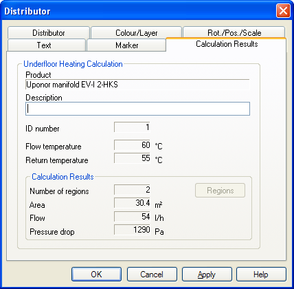
Calculation results for distributor.
Room list will display the results as well, and here you can overrule the pipe spacing distance and change requirements for a new calculation.
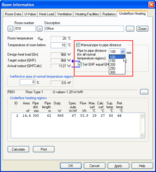
Room properties. Calculation results at the bottom.
If you want to make a report about floor heating calculation, select the button "Print" from Floor heating calculation and select the required report setup.
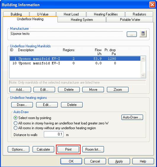
Print from Building dialog.
Click here to see a finished report.
< Previous Chapter - Next Chapter >